
 This page is not fully translated, yet. Please help completing the translation.
(remove this paragraph once the translation is finished)
ISO 17850: Distortion Test
Overview
This International Standard specifies the test methods for geometric distortion of digital cameras.
Standard: ISO 17850:2015
Photography — Digital cameras — Geometric distortion (GD) measurements
Technical Committee: ISO/TC 42 Photography
Terms and Definitions
1. Geometric distortion <for Digital Still Cameras (DSC)>
Displacement of the subject (located on a plane parallel to the image plane) from its ideal shape in the recorded image.
Entry Note 1: Geometric distortion is mainly caused by variations in lateral magnification across the image field of the camera lens, manifesting as straight lines appearing as curves in the image. Additionally, factors such as rotational asymmetry of the camera lens and positional shift processing during camera imaging may also lead to geometric distortion.
2. TV distortion
Line distortion measured using the conventional TV distortion measurement methods specified in IEC 61146-1 (24 Geometric distortion) or EBU Tech 3249 (2.11 Image height distortion).
Test Methods
Local Geometric Distortion Method
The local geometric distortion test method quantifies the geometric distortion of an optical system by analyzing the imaging deviations of a standard dot pattern. The core process is as follows: first, extract the dot pattern in the image and precisely locate the center position of each dot; then, establish an ideal grid coordinate system with the image center (assuming no distortion at the image center) as the origin, and calculate the average grid spacing through vectors to ensure the algorithm's rotation invariance; finally, obtain the distortion value by calculating the percentage of radial deviation ($D_{local}$) between the actual image height $h^{\prime}$ and the ideal image height $h_{0}^{\prime}$ for each dot.
$$D_{local}=\frac {(h^{\prime}-h_{0}^{\prime})}{h_{0}^{\prime}} \times100\% $$
Where $h^{\prime}$ is the distance from the actual dot position to the image center (i.e., actual image height), and $h_{0}^{\prime}$ is the distance from the ideal dot position to the image center (i.e., ideal image height). If $h^{\prime}$<$h_{0}^{\prime}$, the distortion value is negative, indicating barrel distortion; if $h^{\prime}$>$h_{0}^{\prime}$, the distortion value is positive, indicating pincushion distortion.
 |
| H-value of local geometric distortion |
On the left is the undistorted grid: regular grid with no distortion; in the middle is barrel distortion: the distortion value is negative, and the grid points are concave towards the center; on the right is pincushion distortion: the distortion value is positive, and the grid points are convex away from the center.
Line Geometric Distortion Method
The line geometric distortion method quantifies the linear distortion of an optical system by calculating the line distortion in the horizontal and vertical directions separately, based on the pixel data of the output image.
Horizontal Line Geometric Distortion
When the vertical line $A_{i}$ is closer to the vertical line at the image center than the vertical line $B_{i}$, the following formula is used: $$D_{h_{i}}=2V(B_{i}−A_{i})\prime$$ Otherwise, the following formula is used: $$D_{h_{i}}=2V(A_{i}−B_{i})\prime$$ Where: i = subscript representing each image height; $A_{i}$, $B_{i}$, and V shall be expressed in the number of pixels of the output image.
 |  |  |
| Pincushion distortion | Barrel distortion | Mustache distortion |
Vertical Line Geometric Distortion
Assuming the maximum value of the output image width is $\alpha_{i}$ and the minimum value is $\beta_{i}$, and the number of pixels on the short side of the output image frame is V.
If the horizontal line $\alpha_{i}$ is closer to the horizontal line passing through the image center than the horizontal line $\beta_{i}$, the following calculation is used:
$$D_{v_{i}}=\frac{(B_{i}−A_{i})}{2V}\prime$$
Otherwise, the following calculation is used: $$D_{v_{i}}=\frac{(\alpha_{i}−\beta_{i})}{2V}\prime$$
Where: i represents the subscript for each image width; $\alpha_{i}$, $\beta_{i}$, and V are all expressed in the number of pixels of the output image.
 |  |  |
| Barrel distortion | Pincushion distortion | Mustache distortion |
Total Line Geometric Distortion
The line geometric distortion for each dimension is $D_{linei}$:
$$D_{\text{line}i} =
\begin{cases}
\left( \dfrac{Dhi}{|Dhi|} \right) \times \sqrt{Dhi^{2} + Dvi^{2}}\% & \text{若 } |Dhi| > |Dvi| \\
\left( \dfrac{Dvi}{|Dvi|} \right) \times \sqrt{Dhi^{2} + Dvi^{2}}\% & \text{若 } |Dhi| \leq |Dvi|
\end{cases}$$
The formula for its absolute value is expressed as:
$$\left| D_{\text{line}i} \right| = \sqrt{Dhi^{2} + Dvi^{2}}\%$$
The final total line geometric distortion $ D_{\text{line}} $ is defined as the maximum value among all $ \left| D_{\text{line}i} \right| $.
How to Test Distortion in the Laboratory?
Test Equipment
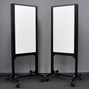 | 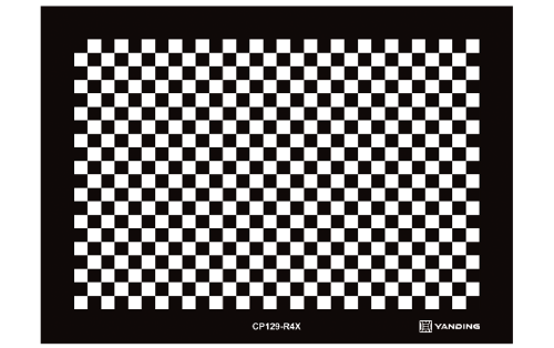 | 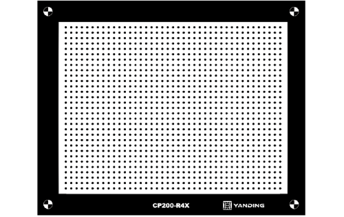 |
| LS-CCXL-2S06-IR V5 Multi-CCT LED Fill Light Source | CP 129 Black and White Checkerboard | CP200 Reflective DOT Distortion Test Chart |
RIQA Analysis and Result Interpretation
The dot pattern and checkerboard test algorithm processes in Yanding's RIQA—Camera Image Quality Analysis Software Distortion Module both comply with the ISO 17850 test standard. The Optical Distortion data output by RIQA is based on the local geometric distortion test method.



